邮箱:510406164@qq.com
惠州市众佳电子有限公司
Huizhou Zhongjia Electronics Co., Ltd.
众佳电子

全国服务热线
13714669926全国服务热线
13714669926Product Center
服务热线
15814620810
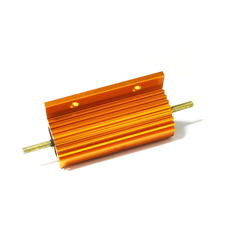
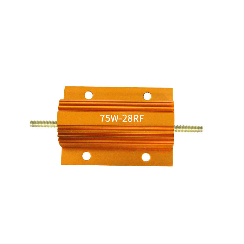
·Rated power: 75W
·Resistance range: 0.01~39K
·Maximum accuracy: ± 1%
·Resistance technology: wire wound resistance
·Packaging material: Industrial 6063 aluminum material
·Packaging method: molded, sand filled
·Installation method: fixed with screws
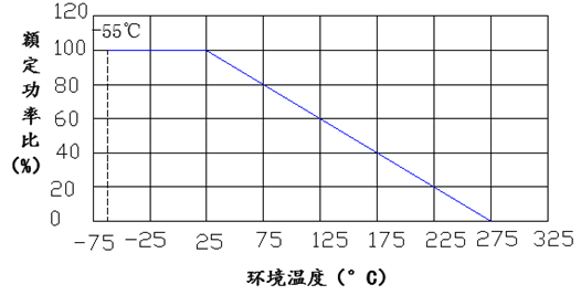
·Working temperature range: -55 ℃~275 ℃
·Dimensions: L=66mm, W=48mm, H=26mm (standard)
Application areas: frequency converters, camera LEDs, car lights
■ Product features
Golden aluminum shell resistors are called metal aluminum shell resistors, non inductive aluminum shell resistors, gold aluminum shell resistors, LED aluminum shell resistors, yellow aluminum shell resistors, etc. The shell is made of aluminum alloy and has heat dissipation grooves on the surface. It has small volume, high power, high temperature resistance, strong overload capacity, weather resistance, high precision, high stability, and strong structural characteristics, which are conducive to mechanical protection and easy installation.
Gold aluminum shell resistors are the most ideal choice for current sensing resistors, standard low inductance resistors, and high-precision resistors due to their low precision and stable temperature coefficient.
When using gold aluminum shell resistors in the automotive LED light industry, we can provide customers with welding high-temperature wires and different models and colors of clamps.
1. The core resistor core component adopts an insulated and high-temperature resistant ceramic rod as the resistor skeleton, and is uniformly wound with high-quality alloy wire. It is equipped with a metal aluminum shell and sealed with high insulation and non flammability electronic paste or silicon copper molding process, so that the metal aluminum shell and the resistor core component are tightly integrated into a solid and stable entity, which is not affected by external air, vibration, and dust, and has high stability and thermal conductivity.
2. The aluminum shell is made of high-quality industrial 6063 aluminum material and undergoes surface high-temperature anodizing treatment to achieve better appearance and better heat dissipation effect.
3. The lead out end can be made of screw type or perforated end pieces or welded high-temperature wires according to customer needs, making it convenient for customers to connect at will.
■ Specifications, dimensions, and technical specifications
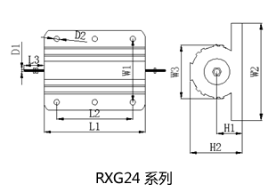
◆ Specifications, dimensions, and units of measurement: mm
|
model |
At 25 ℃ |
Dimensions (mm) |
Weight (g) |
|||||||||||
|
Resistive body (± 1) |
Standard heat dissipation plate (aluminum) |
|||||||||||||
|
L1 |
L2 |
L3 |
W1 |
W2 |
W3 |
H1 |
H2 |
D1 |
D2 |
Surface area |
thickness |
|||
|
RXG24 |
75 |
66 |
47 |
15 |
37 |
48 |
27 |
11.5 |
26 |
*M3 |
4.4 |
995 |
3 |
90 |
*Remarks a and M3 indicate screw specifications; b、 The weight is for reference only.
◆ Technical indicators
|
model |
Rated power at 25 ℃ (W) |
Resistance range (Ω) |
Error (%) |
Temperature coefficient (PPM) |
Voltage endurance |
|
|
Equipped with heat dissipation board |
Without heat dissipation board |
|||||
|
RXG24 |
75 |
40 |
0.01~39K |
±5,±1 |
±250,±100 |
1500 |
*Note a: The gold aluminum shell resistor needs to be used with a standard heat dissipation substrate, and the heat dissipation substrate must be larger than the surface area specified in the specifications.
■ Rated power decreasing diagram
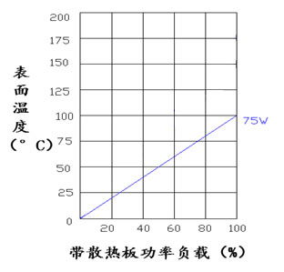
Surface temperature rise chart (with heat dissipation substrate)
Customer selection, for exampleRX24 50W 0.1 Ω± 5%, model: RX24-50-0R1J-BB; Low inductance, add the letter N to the model, for example: N RX24-50-0R1J
|
RX24 |
50 |
0R1 |
J |
B |
B |
|
code |
Rated power |
resistance |
accuracy |
temperature coefficient |
Lead out terminal |
|
RX24 series RXG24 series |
05=5W 10=10W 25=25W 100=100W 300=300W |
0R1=0.1Ω 0R22=0.22Ω 100R=100Ω |
F=±1% G=±2% H=±3% J=±5% K=±10% |
B=±200PPM K=±100PPM Y=±50PPM |
B=Iron cap or screw D=Copper wire |
■ Suggestions for using resistors
It is best to leave 1.5 times the power margin for resistors in circuits. For example, if the voltage in the circuit is 100V and the current is 0.01A, the calculated power is P=100 * 0.01=1W. At this time, a resistor of 1W cannot be used, and 1 * 1.5=1.5W is calculated. If there is no 1.5W resistor, a resistor of 2W is needed.