邮箱:510406164@qq.com
惠州市众佳电子有限公司
Huizhou Zhongjia Electronics Co., Ltd.
众佳电子

全国服务热线
13714669926全国服务热线
13714669926Product Center
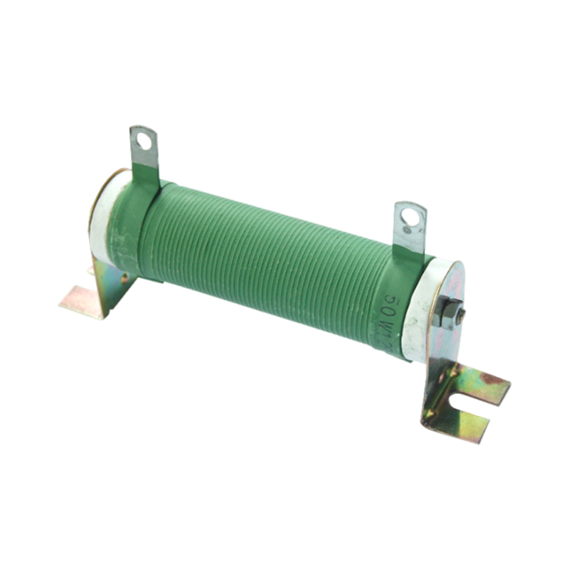
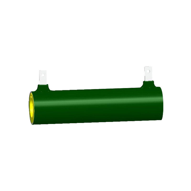
This specification establishes the quality standards and acceptance rules for aluminum shell resistors
Product Features
1. Stable performance, high power, and long service life,.
2. The surface is coated with green non combustible paint.
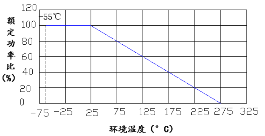
3. Operating environment temperature: -55 ℃ to 275 ℃.
4. Accuracy range: ± 5%
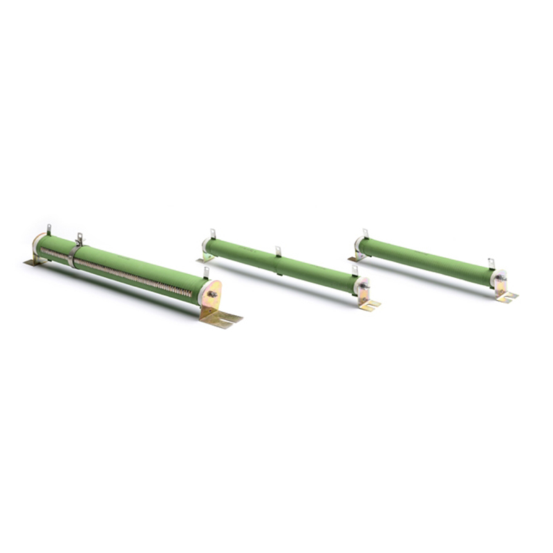
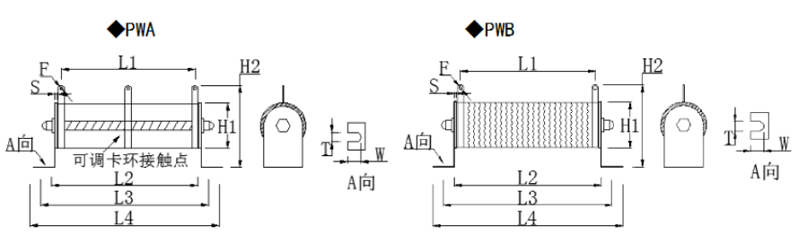
■Specifications, dimensions, and technical indicators
|
Item number |
power |
Resistance range |
Size (mm) |
Maximum operating voltage |
Maximum load voltage |
Insulation withstand voltage |
|||||||||
|
L1±2 |
L2±3 |
L3±3 |
L4±3 |
H1±1 |
H2± 2 |
S ±0.5 |
F±0.5 |
W±1 |
T±0.5 |
||||||
|
PW25 |
25W |
0R22-4K7 |
40 |
60 |
75 |
100 |
20 |
50 |
5 |
3.5 |
13 |
5 |
300V |
300V |
450V |
|
PW50 |
50W |
0R22-10K |
82 |
100 |
114 |
140 |
30 |
58 |
6 |
5 |
14 |
6 |
400V |
400V |
600V |
|
PW100 |
100W |
0R22-15K |
132 |
150 |
174 |
200 |
30 |
58 |
6 |
5 |
14 |
6 |
500V |
500V |
750V |
|
PW150 |
150W |
0R33-18K |
162 |
180 |
194 |
220 |
30 |
58 |
6 |
5 |
14 |
6 |
600V |
600V |
900V |
|
PW200 |
200W |
0R33-22K |
207 |
225 |
240 |
265 |
30 |
58 |
6 |
5 |
14 |
6 |
700V |
700V |
1000V |
|
PW250 |
250W |
0R33-24K |
292 |
310 |
324 |
350 |
30 |
58 |
6 |
5 |
14 |
6 |
900V |
900V |
1300V |
|
PW300 |
300W |
0R33-27K |
258 |
270 |
285 |
328 |
41 |
85 |
7.8 |
6 |
23 |
6 |
1000V |
1000V |
1450V |
|
PW400 |
400W |
0R33-30K |
322 |
344 |
360 |
406 |
41 |
85 |
7.8 |
6 |
23 |
6 |
1500V |
1500V |
2200V |
|
PW500 |
500W |
0R33-33K |
322 |
344 |
355 |
406 |
51 |
95 |
7.8 |
6 |
26 |
8.5 |
1600V |
1600V |
2300V |
|
PW1000 |
1000W |
0R33-36K |
290 |
315 |
325 |
375 |
71 |
110 |
10 |
8 |
32 |
8.5 |
1600V |
1600V |
2300V |
|
PW1500 |
1500W |
0R33-39K |
405 |
420 |
435 |
505 |
71 |
110 |
10 |
8 |
32 |
8.5 |
1700V |
1700V |
2400V |
|
PW2000 |
2000W |
0R33-43K |
495 |
525 |
540 |
610 |
71 |
110 |
10 |
8 |
32 |
8.5 |
1800V |
1800V |
2550V |
*Note: The dimensions are for reference only. Specific dimensions and selection need to be consulted
■characteristic parameter
|
Test project |
Test conditions |
performance |
|
temperature coefficient |
Measure the resistance values at room temperature and 100 ℃ respectively, and calculate the resistance change rate per degree. |
±300ppm℃ |
|
Short term overload |
Apply 10 times the rated voltage or maximum load voltage (whichever is lower) for 5 seconds. |
ΔR≤±(2%R 0.05Ω) |
|
Resistance to welding heat |
Immerse in a tin furnace at 350 ℃± 10 ℃ for 2-3 seconds. |
ΔR≤±(1%R 0.05Ω) |
|
Weldability |
In a 265 ℃± 5 ℃ tin furnace for 2-3 seconds. |
Solder area coverage rate of over 95% |
|
Temperature cycle |
Place at -55 ℃ for 30 minutes, then at 25 ℃ for 10-15 minutes, then at 125 ℃ for 30 minutes, and then at 25 ℃ for 10-15 minutes, in a total of 5 cycles. |
ΔR≤±(1%R 0.05Ω) |
|
Moisture resistant load life |
In a constant temperature and humidity chamber with a temperature of 40 ± 2 ℃ and a relative humidity of 90%, apply the rated voltage or maximum operating voltage (whichever is lower) for a total of 1000 hours (1.5 hours on, 0.5 hours off) |
ΔR≤±(5%R 0.05Ω) |
|
Temperature resistant load life |
Apply rated voltage or maximum operating voltage (whichever is lower) in a 70 ± 2 ℃ constant temperature chamber for 1000 hours (1.5 hours on, 0.5 hours off) |
ΔR≤±(5%R 0.05Ω) |
■Rated power reduction diagram
■Order codeFor example: PW 100W 100R ± 5%, code: PW100JB101
|
PW |
50 |
J |
B |
101 |
nothing |
|
Product model |
size |
accuracy |
packing |
resistance |
specific code |
|
PW high-power resistor PWA sliding high-power resistor PWB ripple high-power resistor
|
60=60W 100=100W 250=250W 1000=1000W
|
J=±5%
|
B=Bulk |
0R1=0.1Ω 0R22=0.22Ω 470=47Ω 471=470Ω 472=4.7KΩ
|
■Suggestions for using resistors
It is best to leave a power margin of 1.5 times for resistors in circuits, such as a voltage of 100V and a current of 0.01A, to calculate the power
P=100*0.01=1W, At this point, a resistor of 1W cannot be used. The calculation shows that 1 * 1.5=1.5W. Without a resistor of 1.5W, 2W of electricity is required
Resistance.
Resistance should not exceed its maximum operating voltage during use, for example, the maximum operating voltage for a resistor of 1/4W 10K is
V==50V, Not 250V in 4.0. Or 1/4W 1M, calculate V==500V
The maximum operating voltage at this time is 250V in 4.0, instead of the calculated 500V, take the smaller of the two.
■Experimental project
◆solderability test:
Tilt one end of the wire of the tested resistor at about 45 ℃ and immerse it in a 265 ℃ 5 ℃ tin furnace for 3 seconds, then remove it and inspect its adhesion (see
The situation involves the use of soldering flux. The coverage rate of soldering area is over 95%.
◆Short term overload testing and calculation method:
First, calculate 10 times the rated power of the resistor to be tested based on its resistance value and wattage. If the voltage at 10 times the rated power exceeds the maximum load voltage of the resistor at that wattage, the maximum load voltage of the resistor at that wattage shall be used as the rated voltage. For example, the maximum load voltage of carbon film 1/4W is 500V, and the rated voltage (V=* 2.5) at 2.5 times the rated voltage (V=* 2.5) of 240K Ω is 612.3V. At this time, the maximum load voltage shall still be calculated at 500V instead of 612.3V. The maximum load voltage calculated on a regular basis using non wave alternating current or direct current must be applied for 5 seconds, and the result must be left unloaded for about 30 minutes without any abnormal resistance. The rate of change of its resistance before and after testing shall not exceed the various resistance standards determined by the characteristic parameters.
Change rate=(R2-R1)/R1 * 100%
R1: pre test resistance value R2: post test resistance value
◆Long life test:
First, fix the resistors to be tested in the measuring clip and arrange them in a way that does not affect the temperature or excessive ventilation between them. In the above article
After the completion of the test, add the rated voltage of the measured resistance. The process of applying voltage is to apply voltage for 90 minutes and then stop for 30 minutes
The clock is cycled for 1000 hours and then placed at a constant temperature to measure its resistance. The calculation of the rate of change shall not exceed the characteristics
Various resistance standards determined by parameters.
◆Temperature coefficient test
First, measure the resistance R1 of the pre tested resistor at t1=25 ℃ at room temperature, and place it in a resin tank at t2=125 ℃ for about 5 minutes
At the same time, measure its resistance R2 and determine whether the temperature coefficient (T.C.R) of the resistor is within its required range using the following formula.
Temperature coefficient TCR=*
◆Temperature cycling experiment
Leave at -55 ℃ for 30 minutes, then at 25 ℃ for 15 minutes, then at 125 ℃ for 30 minutes, and finally at 25 ℃
Leave it for 5 minutes and repeat 5 times in total. As shown in the table below
|
Cycle in sequence |
temperature |
Placement time |
|
1 |
-55℃ |
30 Minutes |
|
2 |
25℃ |
15 minutes |
|
3 |
125℃ |
30 Minutes |
|
4 |
25℃ |
15 minutes |
◆Moisture resistance test
Resistors are placed in a constant temperature and humidity chamber with a temperature of 40 ± 2 ℃ and a relative humidity of 90%. The rated voltage or maximum operating voltage (whichever is lower) is applied for a total of 1000 hours, and a cycle of 1.5 hours of pressure and 0.5 hours of power-off is considered. After completion, measure its resistance by placing it in a constant temperature state.
The calculated rate of change shall not exceed the various resistance standards determined by the characteristic parameters.
◆Temperature resistance load test
Apply the rated voltage or maximum operating voltage (whichever is the minimum) to the resistor in a constant temperature box at 70 ± 2 ℃ for 1000 hours, and break after 1.5 hours of pressure
Electricity 0.5 is one cycle. After completion, measure its resistance by placing it in a constant temperature state. The calculated rate of change shall not exceed the various resistance standards determined by the characteristic parameters.
■Standard resistance value of resistor
|
E24 5% |
1.0 |
1.1 |
1.2 |
1.3 |
1.5 |
1.6 |
1.8 |
2.0 |
2.2 |
2.4 |
2.7 |
3.0 |
3.3 |
3.6 |
3.9 |
4.3 |
|
4.7 |
5.1 |
5.6 |
6.2 |
6.8 |
7.5 |
8.2 |
9.1 |
|||||||||
|
E48 2% |
1.00 |
1.05 |
1.10 |
1.15 |
1.21 |
1.27 |
1.33 |
1.40 |
1.47 |
1.54 |
1.62 |
1.69 |
1.78 |
1.87 |
1.96 |
2.05 |
|
2.15 |
2.26 |
2.37 |
2.49 |
2.61 |
2.74 |
2.87 |
3.01 |
3.16 |
3.32 |
3.48 |
3.65 |
3.83 |
4.02 |
4.22 |
4.42 |
|
|
4.64 |
4.87 |
5.11 |
5.36 |
5.62 |
5.90 |
6.19 |
6.49 |
6.81 |
7.15 |
7.50 |
7.87 |
8.25 |
8.66 |
9.09 |
9.53 |
|
|
E96 1% |
1.00 |
1.02 |
1.05 |
1.07 |
1.10 |
1.13 |
1.15 |
1.18 |
1.21 |
1.24 |
1.27 |
1.30 |
1.33 |
1.37 |
1.40 |
1.43 |
|
1.47 |
1.50 |
1.54 |
1.58 |
1.62 |
1.65 |
1.69 |
1.74 |
1.78 |
1.82 |
1.87 |
1.91 |
1.96 |
2.00 |
2.05 |
2.10 |
|
|
2.15 |
2.21 |
2.26 |
2.32 |
2.37 |
2.43 |
2.49 |
2.55 |
2.61 |
2.67 |
2.74 |
2.80 |
2.87 |
2.94 |
3.01 |
3.09 |
|
|
3.16 |
3.24 |
3.32 |
3.40 |
3.48 |
3.57 |
3.65 |
3.74 |
3.83 |
3.92 |
4.02 |
4.12 |
4.22 |
4.32 |
4.42 |
4.53 |
|
|
4.64 |
4.75 |
4.87 |
4.99 |
5.11 |
5.23 |
5.36 |
5.49 |
5.62 |
5.76 |
5.90 |
6.04 |
6.19 |
6.34 |
6.49 |
6.65 |
|
|
6.81 |
6.98 |
7.15 |
7.32 |
7.50 |
7.68 |
7.87 |
8.06 |
8.25 |
8.45 |
8.66 |
8.87 |
9.09 |
9.31 |
9.53 |
9.76 |
|