邮箱:510406164@qq.com
惠州市众佳电子有限公司
Huizhou Zhongjia Electronics Co., Ltd.
众佳电子

全国服务热线
13714669926全国服务热线
13714669926Product Center
服务热线
15814620810
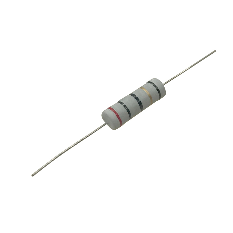
Rated power: 1/4W
Resistance range: 1 Ω~10M Ω
Maximum accuracy: ± 0.1%
Resistance Technology: Membrane Resistors
Packaging material: Nickel chromium alloy film
Packaging method: vacuum coating
Installation method: Welding installation
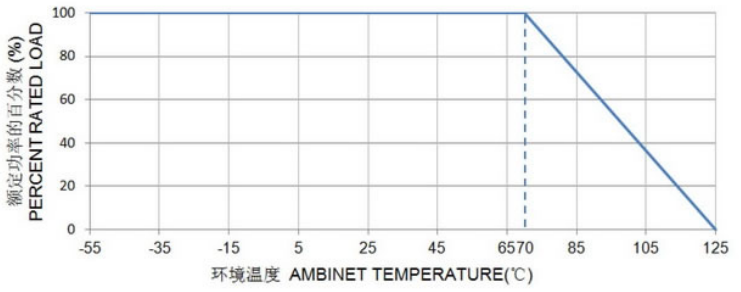
Working temperature range: -55~125 ℃
Dimensions: L=6.3mm D=2.3mm
Application areas: Home appliances, communications, instruments and meters
Product Introduction
main features
1. Compared to precision plug-in resistors and wire wound resistors, it has a compact and exquisite appearance. If it is used for some small-sized products, it will save a lot of space. The consistency of soldering on the surface mount machine is good, and the efficiency is high.
2. The highest accuracy can reach 0.01%, and the lowest temperature coefficient can reach 5PMM.
3. The size range is wide, with a minimum of 0201 and a maximum of 2512.
4. High cost-effectiveness, about twice as cheap as cylindrical metal film resistors of the same specifications, and even more in some specifications.
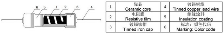
Structural diagram
External dimensions and main technical indicators
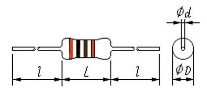
Dimensions Unit: mm
|
model |
External dimensions(mm) |
|||
|
L |
D |
l |
d |
|
|
RJ14 |
6.3±0.5 |
2.3±0.3 |
27±2 |
0.50±0.05 |
Main technical indicators
|
model |
Rated power(W) |
Resistance range(Ω) |
accuracy(%) |
Element limit resistance(V) |
Voltage endurance(V) |
temperature coefficient(PPM/℃) |
|
RJ14 |
1/4 |
1Ω~10MΩ |
±0.1% |
250 |
350 |
±25 |
Power consumption reduction curve chart
Main inspection items, test methods, and performance requirements
|
Inspection items |
performance requirement |
test method |
|
Weldability |
Infiltration area≥95% |
Welding groove method 235±5℃,2s |
|
Terminal tensile strength |
ΔR≤±(1%R 0.05Ω) |
10N,30s |
|
Steady damp-heat |
ΔR≤±(5%R 0.1Ω) |
40±2℃,93±3%RH,1000h |
|
Vibration |
ΔR≤±(1%R 0.05Ω) |
10~500Hz,0.75mmm or 98m/s2,6h |
|
Resistance to welding heat |
ΔR≤±(1%R 0.05Ω) |
260±5℃ 10±1s |
|
Temperature Rapid Culture |
ΔR≤±(1%R 0.05Ω) |
-55℃,30min/125℃,30min,5cycles |
|
Durability at 70 ℃ |
ΔR≤±(5%R 0.1Ω) |
70±2℃,PR,1000h |
|
overload |
ΔR≤±(1%R 0.05Ω) |
2.5 VR,5s |
Customer selection example: RJ 1/4W 20 Ω± 5%, model: RJ-14-20R-J
|
RJ |
14 |
20R |
J |
|
code |
Rated power |
resistance |
accuracy |
|
RJ series |
13=1/6W 14/14S=1/4W 15/15S=1/2W 16/16S=1W 17/17S=2W |
0R1=0.1Ω 0R22=0.22Ω 100R=100Ω |
B=±0.1% |
Suggestions for using resistors
It is best to leave 1.5 times the power margin for resistors in circuits. For example, if the voltage in the circuit is 100V and the current is 0.01A, the calculated power P=100 * 0.01=1W. At this time, a resistor of 1W cannot be used, and 1 * 1.5=1.5W is calculated. If there is no 1.5W resistor, a resistor of 2W is needed.
Resistors should not exceed their maximum operating voltage during use