邮箱:510406164@qq.com
惠州市众佳电子有限公司
Huizhou Zhongjia Electronics Co., Ltd.
众佳电子

全国服务热线
13714669926全国服务热线
13714669926Product Center
服务热线
15814620810
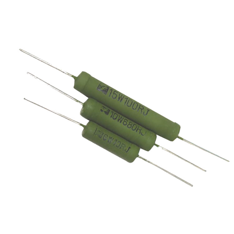
·Rated power: 10W
·Resistance range: R1~51K
·Maximum accuracy: ± 0.1%
·Resistance technology: wire wound resistance
·Packaging material: flame retardant paint or enamel
·Packaging method: painted
·Working temperature range: -55 ℃~155 ℃
·Dimensions: L=35mm W=7mm
Application areas: Telecommunications, Instrumentation
■ Product features
1. By using professional sealing or pressing equipment to tightly bond the copper wire cap with the resistance ceramic body, the stability of the resistance is ensured.
2. The basic ceramic for resistors is made of alumina ceramic or talc ceramic, ensuring good stability and heat dissipation.
3. Wrapped with metal alloy wire and then sealed with non combustible paint, it has the characteristics of small size, good heat resistance, low temperature coefficient, high resistance accuracy, excellent short-term overload performance, and no change in resistance value over the years. It can be made into a non inductive type, and the specifications and dimensions can be made according to customer requirements.
4. We can produce horizontal installation, vertical installation, or molded vertical installation according to customer requirements.
■ Structural diagram

■ Specifications, dimensions, and technical specifications

◆ Specifications, dimensions, and units of measurement: mm
|
model |
Rated power (W) |
Dimensions (mm) |
|||
|
L±2 |
D±1 |
d±0.05 |
1±3 |
||
|
RX21 |
10W |
35 |
7 |
0.8 |
25 |
*Please note that if the customer has special requirements, customization can be negotiated.
◆ Technical indicators
|
model |
Rated power (W) |
Temperature coefficient (PPM/℃) |
Resistance range (Ω) |
Rated power |
Temperature range for use |
|
|
0.1%, 0.25%, 0.5% |
1%, 3%, 5% |
|||||
|
RX21 |
10W |
±25,±50,±100,±250 |
R1~51K |
R1~51K |
±70℃ |
-55℃~ 155℃ |
■ Power consumption reduction curve chart

■ Performance indicators
|
Experimental project |
performance requirement |
test method |
|
Short term overload |
△R≤±(1%R 0.05Ω) |
10V,5S |
|
Rapid temperature changes |
△R≤±(1%R 0.05Ω) |
55℃/275℃,30min 5cycle |
|
Resistance to welding heat |
△R≤±(1%R 0.05Ω) |
125℃,16H/55℃,RH93±3%,24h/-55℃,2h/15~35℃,8.5kpa,1h |
|
Climate sequence |
△R≤±(5%R 0.1Ω) |
350±10℃,3.5 0.5s |
|
Durability at 70 ℃ |
△R≤±(5%R 0.1Ω) |
70±2℃,PR,1000h |
Customer selection, for exampleRX21 10W 30K Ω± 1% temperature coefficient is ± 100PPM/℃, model: RX21-10-30KR-FK; Low inductance, add the letter N to the model, for example: N RX21-10-30KR-FK
|
RX21 |
10 |
30KR |
J |
B |
|
code |
Rated power |
resistance |
accuracy |
temperature coefficient |
|
RX21 series |
05=5W 10=10W 25=25W 100=100W 300=300W |
0R1=0.1Ω 0R22=0.22Ω 100R=100Ω |
B=±0.1% C=±0.25% D=±0.5% F=±1% H=±3% J=±5% |
L=±250PPM B=±200PPM K=±100PPM Y=±50PPM |
■ Suggestions for using resistors
It is best to leave 1.5 times the power margin for resistors in circuits. For example, if the voltage in the circuit is 100V and the current is 0.01A, the calculated power is P=100 * 0.01=1W. At this time, a resistor of 1W cannot be used, and 1 * 1.5=1.5W is calculated. If there is no 1.5W resistor, a resistor of 2W is needed.