邮箱:510406164@qq.com
惠州市众佳电子有限公司
Huizhou Zhongjia Electronics Co., Ltd.
众佳电子

全国服务热线
13714669926全国服务热线
13714669926Product Center
服务热线
15814620810
·Resistance range: 0.39-3.6K
·Maximum accuracy: ± 5%
·Resistance technology: wire wound resistance
·Packaging material: Ceramic
·Packaging method: filling
·Installation method: Welding installation
·Working temperature range: -55~155 ℃
·Dimensions: L=63mm, W=12.5mm, H=12.5mm
Application areas: power adapters, audio equipment, instruments and meters
■ Product Introduction
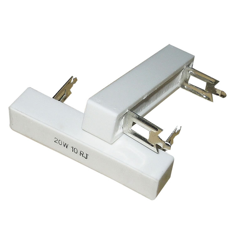
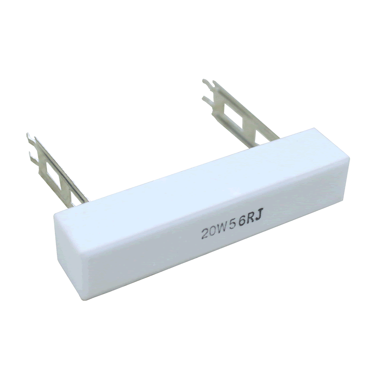
Cement resistors are made by winding resistance wires around non alkaline heat-resistant ceramic parts, protecting and fixing them with heat-resistant, moisture resistant, and corrosion-resistant materials, and placing the wound resistance body in a square ceramic frame. They are filled and sealed with special non combustible heat-resistant cement. The outer side of the cement resistor is mainly made of ceramic material.
Cement resistor is a resistor sealed with cement (actually not cement but refractory mud, which is commonly known as). The resistor wire is wound around a non alkaline heat-resistant ceramic piece, protected and fixed with heat-resistant, moisture resistant, and corrosion-resistant materials, and the wound resistor body is placed in a square porcelain frame, filled and sealed with special non combustible heat-resistant cement. There are two types of cement resistors: ordinary cement resistors and cement wound resistors. The appearance of the cement resistor is shown in the diagram. Cement resistor is a type of wire wound resistor, which belongs to high-power resistors and can allow larger currents to pass through. Its function is the same as that of a general resistor, but it can be used in situations with high current, such as being connected in series with an electric motor to limit the starting current of the motor. The resistance value is generally not large.
Cement resistors have the characteristics of small size, shock resistance, moisture resistance, heat resistance, good heat dissipation, and low price, and are widely used in power adapters, audio equipment, audio dividers, instruments, meters, televisions, automobiles, and other equipment.
■ Main features
1. Characteristics such as shock resistance, moisture resistance, heat resistance, good heat dissipation, and low price.
2. Completely insulated, suitable for printed circuit boards.
3. Wrap the wire around the ceramic rod and then weld the joint to produce precise resistance values and extend its lifespan.
4. The high resistance value is made by using metal oxide film (MO) instead of winding method.
5. Excellent heat resistance, low temperature coefficient of resistance, and linear variation.
6. Resistant to short-term overload, low noise, and resistance unchanged over the years.
7. Good explosion-proof performance, providing protection.
■ Structural diagram

■ External dimensions and main technical indicators

◆ Dimensions Unit: mm
|
model |
Rated power (W) |
Dimensions (mm) |
|||
|
L |
W |
H |
P |
||
|
SQZ(RX27-3) |
20W |
63±2 |
12.5±1 |
12.5±1 |
48±1.5 |
Main technical indicators
|
model |
Rated power (W) |
Resistance range (Ω) |
Voltage endurance (V) |
Accuracy (%) |
Temperature coefficient (PPM/℃) |
|
|
Resistance wire |
Resistive film |
|||||
|
SQZ(RX27-3) |
20W |
0.39~3.6K |
1000 |
±5%,±10% |
±250 |
|
■ Power consumption reduction curve chart

Main inspection items, test methods, and performance requirements
|
Inspection items |
performance requirement |
test method |
|
Weldability |
Infiltration area ≥ 95% |
Welding groove method 235 ± 5 ℃, 2s |
|
Terminal tensile strength |
ΔR≤±(1%R 0.05Ω) |
20N,30s |
|
Steady damp-heat |
ΔR≤±(5%R 0.1Ω) |
40±2℃,93±3%RH,1000h |
|
Vibration |
ΔR≤±(1%R 0.05Ω) |
10~500Hz,0.75mmm or 98m/s2,6h |
|
Resistance to welding heat |
ΔR≤±(1%R 0.05Ω) |
260±5℃ 10±1s |
|
Temperature Rapid Culture |
ΔR≤±(1%R 0.05Ω) |
-55℃,30min/155℃,30min,5cycles |
|
Room temperature durability |
ΔR≤±(5%R 0.1Ω) |
Room temperature, PR, 1000h |
|
overload |
ΔR≤±(1%R 0.05Ω) |
10 PR,5s |
Customer selection, for exampleSQM 5W 20 Ω± 5%, Model: SQM-5-20R-J
|
SQM |
5 |
20R |
J |
B |
|
code |
Rated power |
resistance |
accuracy |
temperature coefficient |
|
SQM (RX27-5) series |
05=5W 10=10W 25=25W 100=100W 300=300W |
0R1=0.1Ω 0R22=0.22Ω 100R=100Ω |
J=±5% |
L=±250PPM |
■ Suggestions for using resistors
It is best to leave 1.5 times the power margin for resistors in circuits. For example, if the voltage in the circuit is 100V and the current is 0.01A, the calculated power is P=100 * 0.01=1W. At this time, a resistor of 1W cannot be used, and 1 * 1.5=1.5W is calculated. If there is no 1.5W resistor, a resistor of 2W is needed.