邮箱:510406164@qq.com
惠州市众佳电子有限公司
Huizhou Zhongjia Electronics Co., Ltd.
众佳电子

全国服务热线
13714669926全国服务热线
13714669926Product Center
服务热线
15814620810
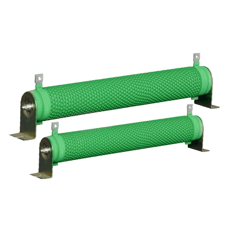
·Rated power: 80W
·Resistance range: 0R5~5R1
·Maximum accuracy: ± 5%
·Resistance technology: wire wound resistance
·Packaging material: Nano silicone coating
·Packaging method: painted
·Working temperature range: -55 ℃~315 ℃
·Dimensions: L=196mm W=62mm
Application areas: elevators, cranes, rolling mills, wire drawing machines, centrifuges, load testing
The wire wound high-power resistor produced by Wanliansheng uses high-frequency ceramic tubes instead of clay tubes. High frequency ceramic tubes have the characteristics of durability, high power, high heat dissipation, and small size. The surface coating is entirely made of Taiwanese nano silicone coating, which is green, environmentally friendly, non-toxic, odorless, and ensures stable power, good heat dissipation, and safety. All hardware accessories are thickened, widened, and installed securely and safely.
1. Resistant to high current impact, with good power load capacity and a wide power range.
2. Fully welded structure, the product has high reliability.
3. Surface vertical ripples are beneficial for heat dissipation and reducing parasitic inductance. High flame retardant coatings are selected to effectively protect the resistance wire from oxidation and extend its service life.
■ Structural diagram

■ Specifications, dimensions, and technical specifications

◆ Specifications, dimensions, and units of measurement: mm
|
model |
Rated power (W) |
Dimensions (mm) |
||||||||||
|
L1±2 |
L2±5 |
L3±3 |
D±2 |
B±1 |
S±2 |
H±1 |
H1±3 |
N±2 |
Φd±1 |
T±0.5 |
||
|
RXBW |
80W |
152 |
174 |
196 |
28 |
6.5 |
27 |
28 |
62 |
9 |
4.5 |
1.2 |
*Please note that if the customer has special requirements, customization can be negotiated.
◆ Technical indicators
|
model |
Rated power (W) |
Resistance range (Ω) |
Allowable deviation of resistance value (%) |
Maximum operating voltage (V) |
Voltage endurance (V) |
Temperature coefficient (PPM/℃) |
|
RXBW |
80W |
0.5~5.1 |
J(±5%) |
√PR |
1500 |
±250 |
■ Power consumption reduction curve chart

■ Performance indicators
|
Experimental project |
performance requirement |
test method |
|
Weldability |
Infiltration area ≥ 95% |
Welding groove method 235 ± 5 ℃, 2s |
|
Terminal tensile strength |
△R≤±(1%R 0.05Ω) |
20N,30s |
|
Steady damp-heat |
△R≤±(2%R 0.05Ω) |
40±2℃,93±3RH,1000h |
|
Vibration |
△R≤±(1%R 0.05Ω) |
10~500Hz,0.75mmm or 98m/s2,6h |
|
collision |
△R≤±(1%R 0.05Ω) |
Frequency 40-80 times/min 2000 times |
|
Surface temperature rise |
≤275℃ |
Apply rated power load PR |
|
Room temperature durability |
△R≤±(5%R 0.05Ω) |
Room temperature PR, 1000h |
|
overload |
△R≤±(2%R 0.05Ω) |
10PR,5s |
Customer selection, for exampleRXBW 50W 10 Ω± 5%, Model: RXBW-50-10R-J
|
RXBW |
50 |
10R |
J |
|
code |
Rated power |
resistance |
accuracy |
|
RXBW series |
05=5W 10=10W 25=25W 100=100W 300=300W |
0R1=0.1Ω 0R22=0.22Ω 100R=100Ω |
J=±5% K=±10% |
■ Suggestions for using resistors
It is best to leave 1.5 times the power margin for resistors in circuits. For example, if the voltage in the circuit is 100V and the current is 0.01A, the calculated power is P=100 * 0.01=1W. At this time, a resistor of 1W cannot be used, and 1 * 1.5=1.5W is calculated. If there is no 1.5W resistor, a resistor of 2W is needed.
.png)